When you make a photograph with a DLSR Camera, image orientation is no question. What you see with your eyes, what your camera shows you in the display, and the final image will have the same orientation.
However, there is no way to “look” through a dedicated astro camera. Image processing software tends to flip or rotate the image to make the orientation “right”, the only problem being that it doesn’t necessarily tell you what is has done. The steering software of the telescope mount performs a so called meridian flip sometime before or after meridian transit of your object. This leads to a rotation of your image by 180° in the middle of an observation session. Finally, using a reflector telescope with a primary and a secondary mirror will introduce an additional flip of your image.
This becomes a real problem when you have a tilt in your optical train and you want to correct for it with a camera tilting unit (CTU). A CTU typically has three adjustment screws. It is essential to know which corner of the image corresponds to which screw. So to begin, lets have a look at a typical setup with a tube of a reflector telescope, the attached focuser and the CTU with three adjustment (taper) screws. When your CTU is screwed to the camera and the optical train, the adjustment screws may be at any orientation with respect to the focuser and camera sensor.
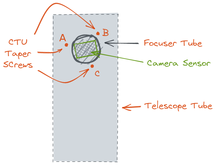
Now you have an image taken with the sensor. It has
- a certain orientation with respect to the sky indicated by a long and a short arrow pointing to the north and west, respectively
- a certain orientation with respect to the taper screws indicated by the dots marked A, B, C
The following sketches show the situation before and after a meridian flip. The meridian flip leads to a rotation of the image by 180° with respect to the sensor and the taper screws. Also included is a sketch mirrored horizontally, because in my experience thats what your imaging software might do in some cases.
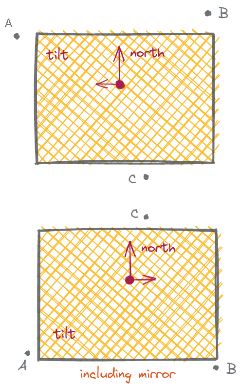
Situation before a meridian flip
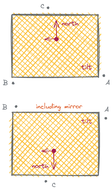
Situation after a meridian flip